Electronic Testing Equipment Guide: Explore Laboratory Instruments, Functions & Measurements
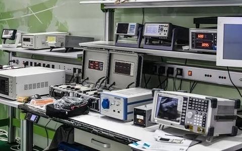
Electronic testing equipment is used to measure, analyze and verify the electrical characteristics and performance of components, circuits and electronic systems. These instruments are used in educational laboratories, research environments, product development, manufacturing facilities and maintenance activities.
Different testing instruments are designed for different measurement requirements. A digital multimeter can measure basic electrical quantities, while an oscilloscope provides a visual representation of changing signals. Other instruments, such as signal generators, electronic loads, spectrum analyzers and logic analyzers, support more specialized testing tasks.
Understanding the functions of these instruments provides a useful foundation for learning how electronic circuits are evaluated.
What Is Electronic Testing Equipment?
Electronic testing equipment refers to instruments used to observe, measure or analyze electrical and electronic parameters.
Common measurement parameters include:
Voltage
Current
Resistance
Capacitance
Inductance
Frequency
Signal amplitude
Power
Impedance
Timing
Waveform characteristics
The choice of equipment depends on the type of circuit, expected signal characteristics and measurement objectives.
Digital Multimeter
A digital multimeter, commonly called a DMM, is one of the most widely used electronic testing instruments.
Depending on the model, it can measure:
DC voltage
AC voltage
DC current
AC current
Resistance
Continuity
Diode characteristics
Capacitance
Frequency
Temperature
Common Functions
Multimeters are useful for checking circuit voltages, measuring component resistance, verifying continuity and identifying basic electrical problems.
Advanced models may include features such as automatic ranging, data logging and computer connectivity.
Oscilloscope
An oscilloscope displays electrical signals as waveforms, normally showing voltage against time.
It can be used to examine:
Signal amplitude
Frequency
Period
Pulse width
Rise time
Fall time
Noise
Distortion
Timing relationships
Important Specifications
Several specifications influence oscilloscope performance.
Bandwidth determines the range of frequencies that can be measured accurately.
Sample rate indicates how frequently the oscilloscope samples the incoming signal.
Record length determines how much waveform data can be stored for analysis.
Channel count determines how many signals can be monitored at the same time.
Oscilloscopes are widely used for digital electronics, analog circuits, embedded systems and communication-related testing.
Function and Signal Generator
A signal generator creates controlled electrical signals that can be applied to a circuit under test.
Common waveforms include:
Sine
Square
Triangle
Ramp
Pulse
Users can typically adjust frequency, amplitude and other signal parameters.
Applications
Signal generators are useful for examining:
Amplifiers
Filters
Oscillators
Audio circuits
Communication circuits
Signal-processing systems
A controlled input allows the response of a circuit to be observed under repeatable conditions.
DC Laboratory Power Supply
A laboratory power supply provides controlled DC voltage and current to a circuit.
Common controls include:
Output voltage
Current limit
Output enable
Multiple output channels
The current-limit function can help restrict the amount of current delivered to a circuit during testing.
Applications
Laboratory power supplies are commonly used for:
Prototype testing
Circuit development
Embedded-system testing
Educational experiments
Component evaluation
LCR Meter
An LCR meter is designed to measure characteristics of passive components.
The name refers to:
L: Inductance
C: Capacitance
R: Resistance
Depending on the instrument, measurements can also include impedance, phase angle and quality factor.
LCR meters are useful when detailed characterization of passive components is required.
Frequency Counter
A frequency counter measures the frequency of an electrical signal.
It can be used for:
Oscillator testing
Clock verification
Signal-generator testing
Timing measurements
Communication-system analysis
Some frequency counters can also measure signal period and related timing parameters.
Electronic Load
An electronic load is used to apply a controlled electrical load to a power source.
It is commonly used for evaluating:
Power supplies
Batteries
DC converters
Adapters
Power-management circuits
Common operating modes include:
Constant current
Constant voltage
Constant resistance
Constant power
Electronic loads are useful when a controlled and adjustable load is required during testing.
Spectrum Analyzer
A spectrum analyzer examines signals in the frequency domain.
Instead of primarily displaying voltage against time, it shows signal components across a range of frequencies.
It can help identify:
Fundamental signals
Harmonics
Spurious signals
Noise
Interference
Frequency peaks
Spectrum analyzers are particularly relevant to RF, wireless and communication-system testing.
Logic Analyzer
A logic analyzer is designed for examining multiple digital signals.
It records changes in digital signal states and displays their timing relationships.
Logic analyzers are commonly used for:
Microcontroller development
Embedded-system debugging
Digital circuit testing
Communication-bus analysis
Timing verification
They can be especially useful when several digital lines need to be observed simultaneously.
Network Analyzer
Network analyzers are used to characterize electrical networks, particularly at higher frequencies.
Depending on the instrument, measurements can include:
Reflection
Transmission
Impedance
Frequency response
Signal loss
A vector network analyzer, or VNA, is commonly used in RF and microwave applications.
Power Analyzer
A power analyzer measures electrical power and related parameters.
Depending on the instrument, measurements may include:
Voltage
Current
Real power
Apparent power
Power factor
Frequency
Harmonic components
Power analyzers are useful for examining power supplies, converters, motors and other electrical equipment.
Electronic Component Testers
Specialized component testers can evaluate individual electronic components.
Depending on the instrument, they may test:
Resistors
Capacitors
Inductors
Diodes
Transistors
LEDs
Semiconductor devices
Some component analyzers can automatically identify component characteristics and display measurement results.
Common Electronic Measurements
Electronic testing involves several fundamental measurement concepts.
Voltage
Voltage represents electrical potential difference between two points. It is normally measured in volts.
Current
Current represents the movement of electric charge through a circuit and is measured in amperes.
Resistance
Resistance describes opposition to current flow and is measured in ohms.
Capacitance
Capacitance represents a component's ability to store electrical charge and is measured in farads.
Inductance
Inductance describes the ability of a component to store energy in a magnetic field and is measured in henries.
Frequency
Frequency indicates how many cycles of a periodic signal occur per second and is measured in hertz.
Impedance
Impedance represents opposition to alternating current and includes both resistive and reactive components.
Accuracy, Precision and Resolution
Understanding instrument specifications is important when evaluating measurement results.
Accuracy
Accuracy indicates how close a measurement is to an accepted or reference value.
Precision
Precision describes how consistently an instrument produces repeated measurements.
Resolution
Resolution indicates the smallest change that the instrument can distinguish or display.
Measurement Range
Measurement range defines the values that can be measured within the instrument's specified operating conditions.
These characteristics should be considered together rather than treating a single specification as an indicator of overall measurement capability.
Electronic Testing Applications
Electronic testing equipment is used across numerous fields.
Research and Development
Engineers and researchers use test instruments to evaluate circuits, components and prototypes.
Education
Laboratories use basic testing instruments to demonstrate concepts involving voltage, current, resistance, signals and circuit behavior.
Manufacturing
Testing equipment can be integrated into production processes to verify electronic assemblies and components.
Embedded Systems
Oscilloscopes, multimeters and logic analyzers can help examine microcontrollers, sensors and digital communication interfaces.
Power Electronics
Electronic loads, oscilloscopes and power analyzers are useful for evaluating power-conversion circuits and power sources.
Communication Systems
Signal generators, spectrum analyzers and network analyzers support testing of RF and communication-related systems.
Choosing Electronic Testing Equipment
The appropriate instrument depends on the testing requirement.
Identify the Measurement
First determine whether the requirement involves voltage, current, resistance, waveform analysis, frequency, power or another parameter.
Consider Signal Characteristics
For changing signals, consider frequency, amplitude, rise time and waveform type.
Check Instrument Specifications
Important specifications may include:
Measurement range
Accuracy
Resolution
Bandwidth
Sample rate
Channel count
Input impedance
Maximum input rating
Consider Connectivity
USB, Ethernet, LAN and other interfaces can be useful for automated testing, data logging and computer-based analysis.
Consider Calibration
Regular calibration or verification may be required depending on the instrument, laboratory procedures and measurement requirements.
Testing Safety
Electronic testing should always follow appropriate laboratory procedures and the manufacturer's documentation.
Important practices include:
Select the correct measurement function.
Verify the expected voltage and current range.
Use suitable probes and cables.
Do not exceed the instrument's input rating.
Inspect test leads before use.
Follow grounding and isolation requirements.
Keep measurement connections organized.
Follow applicable electrical-safety procedures.
Additional precautions may be necessary when working with high-voltage, high-current, high-frequency or energy-storage systems.
Modern Trends in Electronic Testing
Electronic testing equipment is increasingly becoming digital, connected and software-driven.
Important developments include:
Touchscreen interfaces
Automated measurements
Remote instrument control
Computer-based data acquisition
Automated test sequences
Digital waveform analysis
Higher sampling rates
Integrated measurement software
Network-connected instruments
Automated production testing
These technologies can make it easier to collect, store and analyze large quantities of measurement data.
Frequently Asked Questions
What is the most commonly used electronic testing instrument?
A digital multimeter is one of the most common instruments because it supports several basic measurements, including voltage, current and resistance.
What is an oscilloscope used for?
An oscilloscope is used to observe and analyze electrical signals as they change over time.
What is the purpose of a signal generator?
A signal generator produces controlled electrical signals that can be applied to a circuit to examine its response.
What does a spectrum analyzer measure?
A spectrum analyzer examines the frequency components of a signal and can help identify harmonics, interference, noise and other frequency-domain characteristics.
What is an electronic load?
An electronic load provides a controlled load to a power source and allows engineers to examine how the source behaves under different loading conditions.
Conclusion
Electronic testing equipment provides the measurement capabilities required to develop, troubleshoot and evaluate electronic components and systems. Basic instruments such as digital multimeters, laboratory power supplies and signal generators support routine testing, while oscilloscopes, logic analyzers, spectrum analyzers, network analyzers and power analyzers provide more specialized measurement capabilities.
Selecting the right instrument requires consideration of the measurement type, electrical characteristics, accuracy, resolution, bandwidth, safety requirements and testing environment. As laboratories become increasingly connected and automated, modern testing equipment is also incorporating software control, digital analysis and automated measurement functions.
Disclaimer: This article is provided for general informational and educational purposes only. Instrument capabilities, measurement procedures, safety requirements and testing practices vary according to equipment and application. Always consult the manufacturer's documentation and follow applicable laboratory and electrical-safety procedures when using electronic testing equipment.

Related Post...
Electronic Component Manufacturers Guide: Explore Types, Components, Manufacturing & Key Insights
Updated: September 24, 2026
Read More
Electronic Component Manufacturing Guide: Explore Components, Processes, Quality & Technologies
Updated: September 24, 2026
Read More